Tuesday, March 2, 2010
VHDL CODE OF ADDER /SUBTRACTOR
Now consider the VHDL code
--FIRST START WITH A FULL ADDER
--THEN DESIGN XOR GATE
--THEN BIND 4 FULL ADDERS AND 4 XOR GATES
--PURE STRUCTURAL MODELING
--MIXED OR BEHAVIORAL ALSO CAN BE USED
--PREPARED BY BIJOY
LIBRARY IEEE;
USE IEEE.STD_LOGIC_1164.ALL;
ENTITY FA IS
PORT(A,B,CIN:IN STD_LOGIC;SUM,COUT:OUT STD_LOGIC);
END FA;
ARCHITECTURE BEHV OF FA IS
BEGIN
SUM<=A XOR B XOR CIN;
COUT<=(A AND B) OR (B AND CIN) OR (A AND CIN);
END BEHV;
--I AM GOING TO DESIGN AN ENTITY FOR XOR FUNCTION
LIBRARY IEEE;
USE IEEE.STD_LOGIC_1164.ALL;
ENTITY XOR_1 IS
PORT(A,B:IN STD_LOGIC;Y:OUT STD_LOGIC);
END XOR_1;
ARCHITECTURE BEHV OF XOR_1 IS
BEGIN
Y<=A XOR B;
END BEHV;
LIBRARY IEEE;
USE IEEE.STD_LOGIC_1164.ALL;
ENTITY ADD_SUB IS
PORT(A,B:IN STD_LOGIC_VECTOR(3 DOWNTO 0);AD_SB:IN STD_LOGIC;SUM_DIF:OUT STD_LOGIC_VECTOR(3 DOWNTO 0);COUT :OUT STD_LOGIC);
END ADD_SUB;
ARCHITECTURE BEH123 OF ADD_SUB IS
SIGNAL TEMP:STD_LOGIC_VECTOR(3 DOWNTO 0);
SIGNAL C_TEMP:STD_LOGIC_VECTOR(2 DOWNTO 0);
BEGIN
XOR1:ENTITY WORK.XOR_1 PORT MAP(B(0),AD_SB,TEMP(0));
XOR2:ENTITY WORK.XOR_1 PORT MAP(B(1),AD_SB,TEMP(1));
XOR3:ENTITY WORK.XOR_1 PORT MAP (B(2),AD_SB,TEMP(2));
XOR4:ENTITY WORK.XOR_1 PORT MAP (B(3),AD_SB,TEMP(3));
-- INV1:ENTITY WORK.INV PORT MAP (AD_SB,CTRL);
--ADDER:ENTITY WORK.ADDER_4BIT PORT MAP(A,TEMP,SUM,COUT);
FA1:ENTITY WORK.FA PORT MAP (A(0),TEMP(0),AD_SB,SUM_DIF(0),C_TEMP(0));
FA2:ENTITY WORK.FA PORT MAP (A(1),TEMP(1),C_TEMP(0),SUM_DIF(1),C_TEMP(1));
FA3:ENTITY WORK.FA PORT MAP (A(2),TEMP(2),C_TEMP(1),SUM_DIF(2),C_TEMP(2));
FA4:ENTITY WORK.FA PORT MAP (A(3),TEMP(3),C_TEMP(2),SUM_DIF(3),COUT);
END BEH123;
Saturday, February 27, 2010
VHDL MODEL OF SUBTRACTOR
The VHDL code is shown below
--PREPARED BY BIJOY
LIBRARY IEEE;
USE IEEE.STD_LOGIC_1164.ALL;
ENTITY FA IS
PORT(A,B,CIN:IN STD_LOGIC;SUM,COUT:OUT STD_LOGIC);
END FA;
ARCHITECTURE BEHV OF FA IS
BEGIN
SUM<=A XOR B XOR CIN;
COUT<=(A AND B) OR (B AND CIN) OR (A AND CIN);
END BEHV;
-- NOW DESIGN A 4 BIT ADDING UNIT BY CASCADING 4 FULL ADDER UNITS
--STRUCTURAL BINDING OF UNITS ENTITY FA
LIBRARY IEEE;
USE IEEE.STD_LOGIC_1164.ALL;
ENTITY ADDER_4BIT IS
PORT(A,B:IN STD_LOGIC_VECTOR(3 DOWNTO 0);S:OUT STD_LOGIC_VECTOR(3 DOWNTO 0);C:OUT STD_LOGIC);
END ADDER_4BIT;
ARCHITECTURE BEHV OF ADDER_4BIT IS
SIGNAL TEMP:STD_LOGIC:='0';
SIGNAL CAR:STD_LOGIC_VECTOR(2 DOWNTO 0);
BEGIN
FA1:ENTITY WORK.FA PORT MAP(A(0),B(0),TEMP,S(0),CAR(0));
FA2:ENTITY WORK.FA PORT MAP(A(1),B(1),CAR(0),S(1),CAR(1));
FA3:ENTITY WORK.FA PORT MAP(A(2),B(2),CAR(1),S(2),CAR(2));
FA4:ENTITY WORK.FA PORT MAP(A(3),B(3),CAR(2),S(3),C);
END BEHV;
--NOW I AM GOING TO DEVELOP A 4 BIT SUBSTRACTOR
--2'S COMPLEMENT ADDITION IS USING
LIBRARY IEEE;
USE IEEE.STD_LOGIC_1164.ALL;
USE IEEE.STD_LOGIC_UNSIGNED.ALL;
--TO USE "+" FUNCTION
ENTITY SUB_4BIT IS
PORT(AIN,BIN:IN STD_LOGIC_VECTOR(3 DOWNTO 0);DIFF:OUT STD_LOGIC_VECTOR(3 DOWNTO 0);BOR:OUT STD_LOGIC);
END SUB_4BIT;
ARCHITECTURE BEH OF SUB_4BIT IS
SIGNAL TEMP,TEMP1:STD_LOGIC_VECTOR(3 DOWNTO 0);
BEGIN
TEMP<=NOT BIN;
TEMP1<=TEMP+"0001";
ADDERUNIT:ENTITY WORK.ADDER_4BIT PORT MAP(AIN,TEMP1,DIFF,BOR);
END BEH;
VHDL MODEL OF 4 BIT PARALLEL BINARY ADDER
The VHDL code of 4 bit parallel adder is given below
--PREPARED BY BIJOY
LIBRARY IEEE;
USE IEEE.STD_LOGIC_1164.ALL;
ENTITY FA IS
PORT(A,B,CIN:IN STD_LOGIC;SUM,COUT:OUT STD_LOGIC);
END FA;
ARCHITECTURE BEHV OF FA IS
BEGIN
SUM<=A XOR B XOR CIN;
COUT<=(A AND B) OR (B AND CIN) OR (A AND CIN);
END BEHV;
-- NOW DESIGN A 4 BIT ADDING UNIT BY CASCADING 4 FULL ADDER UNITS
--STRUCTURAL BINDING OF UNITS ENTITY FA
LIBRARY IEEE;
USE IEEE.STD_LOGIC_1164.ALL;
ENTITY ADDER_4BIT IS
PORT(A,B:IN STD_LOGIC_VECTOR(3 DOWNTO 0);S:OUT STD_LOGIC_VECTOR(3 DOWNTO 0);C:OUT STD_LOGIC);
END ADDER_4BIT;
ARCHITECTURE BEHV OF ADDER_4BIT IS
SIGNAL TEMP:STD_LOGIC:='0';
SIGNAL CAR:STD_LOGIC_VECTOR(2 DOWNTO 0);
BEGIN
FA1:ENTITY WORK.FA PORT MAP(A(0),B(0),TEMP,S(0),CAR(0));
FA2:ENTITY WORK.FA PORT MAP(A(1),B(1),CAR(0),S(1),CAR(1));
FA3:ENTITY WORK.FA PORT MAP(A(2),B(2),CAR(1),S(2),CAR(2));
FA4:ENTITY WORK.FA PORT MAP(A(3),B(3),CAR(2),S(3),C);
END BEHV;
--getting output properly
--DIRECT INSTANTIATION IS USED
Friday, February 26, 2010
VHDL MODEL OF FULL ADDER
The VHDL code of full adder unit is shown below.
--PREPARED BY BIJOY
LIBRARY IEEE;
USE IEEE.STD_LOGIC_1164.ALL;
ENTITY FA IS
PORT(A,B,CIN:IN STD_LOGIC;SUM,COUT:OUT STD_LOGIC);
END FA;
ARCHITECTURE BEHV OF FA IS
BEGIN
SUM<=A XOR B XOR CIN;
COUT<=(A AND B) OR (B AND CIN) OR (A AND CIN);
END BEHV;
VHDL MODEL OF 8:1(8 INPUT) MULTIPLEXER
Working:If control signal is "000" ,then the first input is transferring to output line.If control signal is "111",then the last input is transferring to output.Similarly for all values of control signals.A simple block diagram of 8:1 multiplexer is shown here.
Now see the VHDL code of 8:1 multiplexer
LIBRARY IEEE;
USE IEEE.STD_LOGIC_1164.ALL;
ENTITY MUX8_1 IS
PORT(DIN:IN STD_LOGIC_VECTOR(7 DOWNTO 0);SEL:IN STD_LOGIC_VECTOR(2 DOWNTO 0);DOUT:OUT STD_LOGIC);
END MUX8_1;
ARCHITECTURE BEH123 OF MUX8_1 IS
BEGIN
PROCESS(DIN,SEL)
BEGIN
CASE SEL IS
WHEN"000"=>DOUT<=DIN(0);
WHEN"001"=>DOUT<=DIN(1);
WHEN"010"=>DOUT<=DIN(2);
WHEN"011"=>DOUT<=DIN(3);
WHEN"100"=>DOUT<=DIN(4);
WHEN"101"=>DOUT<=DIN(5);
WHEN"110"=>DOUT<=DIN(6);
WHEN"111"=>DOUT<=DIN(7);
WHEN OTHERS=>
DOUT<='Z';
END CASE;
END PROCESS;
END BEH123;
Thursday, February 25, 2010
VHDL MODEL OF SERIAL IN PARALLEL OUT SHIFT REGISTER(SERIAL TO PARALLEL CONVERTER)
We already discussed about D flip flops.So now, consider the VHDL code.here I have not designed a register to store the serial information.So you have to apply the serial input bit by bit after each clock pulse.
--CODE OF D FLIP FLOP
LIBRARY IEEE;
USE IEEE.STD_LOGIC_1164.ALL;
ENTITY DFF_1 IS
PORT(D,CLOCK:IN STD_LOGIC;Q,QBAR:OUT STD_LOGIC);
END DFF_1;
ARCHITECTURE FF OF DFF_1 IS
BEGIN
PROCESS(D,CLOCK)
BEGIN
IF RISING_EDGE(CLOCK) THEN
Q<=D;
QBAR<=NOT D;
END IF;
END PROCESS;
END FF;
--SUCCESS GETTING OUTPUT
--NOW DESIGN SHIFT REGISTER
--SERIAL TO PARALLEL CONVERTER AND SERIAL IN PARALLEL OUT SHIFT REGISTER ARE --BASICALLY SAME
LIBRARY IEEE;
USE IEEE.STD_LOGIC_1164.ALL;
ENTITY SERTOPAR IS
PORT(SERIN,CLOCK:IN STD_LOGIC;Q:OUT STD_LOGIC_VECTOR(7 DOWNTO 0));
END SERTOPAR;
ARCHITECTURE BE1 OF SERTOPAR IS
SIGNAL S1,S2,S3,S4,S5,S6,S7,S8:STD_LOGIC;
BEGIN
D1:ENTITY WORK.DFF_1 PORT MAP(SERIN,CLOCK,S1,OPEN);
Q(0)<=S1;
D2:ENTITY WORK.DFF_1 PORT MAP(S1,CLOCK,S2,OPEN);
Q(1)<=S2;
D3:ENTITY WORK.DFF_1 PORT MAP (S2,CLOCK,S3,OPEN);
Q(2)<=S3;
D4:ENTITY WORK.DFF_1 PORT MAP (S3,CLOCK,S4,OPEN);
Q(3)<=S4;
D5:ENTITY WORK.DFF_1 PORT MAP (S4,CLOCK,S5,OPEN);
Q(4)<=S5;
D6:ENTITY WORK.DFF_1 PORT MAP (S5,CLOCK,S6,OPEN);
Q(5)<=S6;
D7:ENTITY WORK.DFF_1 PORT MAP (S6,CLOCK,S7,OPEN);
Q(6)<=S7;
D8:ENTITY WORK.DFF_1 PORT MAP (S7,CLOCK,Q(7),OPEN);
END BE1;
--working properly
--CREATED AND TESTED BY BIJOY
--DATE IS 14/08/2009
MODEL OF D FLIP FLOP
The inputs needed for operation are:
1)D :This input is the actual data input to the flip flop.
2)CLOCK :This is the clock needed for all synchronous circuits.
The outputs needed are:
1)Q :This is the first output of D flip flop.On the active edge of clock(for edge triggered flip flops) the D input is transferring to this output pin.
2)QBAR :This gives the complement of Q.
Working: In my design ,I developed a positive edge triggered flip flop. That is,the D input is transferring to Q during the '0' to '1' (or low to high)transition of CLOCK> If you need a negative edge triggered flip flop ,you can edit this code by replacing RISING_EDGE(CLOCK) by FALLING_EDGE(CLOCK).
VHDL CODE OF D FLIP FLOP
LIBRARY IEEE;
USE IEEE.STD_LOGIC_1164.ALL;
ENTITY DFF_1 IS
PORT(D,CLOCK:IN STD_LOGIC;Q,QBAR:OUT STD_LOGIC);
END DFF_1;
ARCHITECTURE FF OF DFF_1 IS
BEGIN
PROCESS(D,CLOCK)
BEGIN
IF RISING_EDGE(CLOCK) THEN
Q<=D;
QBAR<=NOT D;
END IF;
END PROCESS;
END FF;
--IT IS WORKING PROPERLY
VHDL MODEL OF ROM
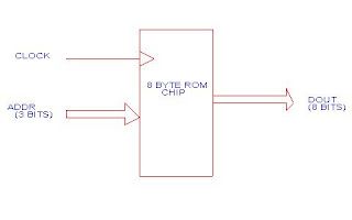
Working:In this design,I used only 8 locations.So I need only 3 bit address bus.Also we need a clock input ,because it is a synchronous circuit.These are the two input ports.And we need an 8 bit output port.If you apply clock,and give any address in the range "000" to "111" as input values,you can see the data from the specified address as output value.
In my code ,the contents of ROM are listed here.
ADDRESS CONTENT
000 00000000
001 00000001
010 00001111
011 00001100
100 00001100
101 00001000
110 00001101
111 00110000
Now the simplified block diagram is given
The VHDL code of ROM chip is given below.This code is useful when you are designing a microprocessor or micro controller.You can use this type of ROM (With more size-You can edit this code) to store program code (Hex code),needed for the working of processor.
LIBRARY IEEE;
USE IEEE.STD_LOGIC_1164.ALL;
USE IEEE.STD_LOGIC_UNSIGNED.ALL;
--prepared by BIJOY K JOSEPH
ENTITY ROM IS
PORT(ADDR:IN STD_LOGIC_VECTOR(2 DOWNTO 0);CLOCK:IN STD_LOGIC;DOUT:OUT STD_LOGIC_VECTOR(7 DOWNTO 0));
END ROM;
ARCHITECTURE BEH123 OF ROM IS
TYPE ROM_ARR IS ARRAY(0 TO 7)OF STD_LOGIC_VECTOR(7 DOWNTO 0);
CONSTANT MEM:ROM_ARR:=
( "00000000","00000001","00001111","00001100","00001100","00001000","00001101","00110000");
BEGIN
PROCESS(CLOCK)
BEGIN
IF RISING_EDGE(CLOCK) THEN
DOUT<=MEM(CONV_INTEGER(ADDR));
END IF;
END PROCESS;
END BEH123;
--success getting output
VHDL MODEL OF PARALLEL TO SERIAL CONVETER
Simply a parallel to serial converter consists of
a)An 8 bit multiplexer,
b)A 3 bit counter.
A simplified logic diagram of the circuit is shown here.
Working:The parallel data is applied at the input of multiplexer.The select input of the multiplexer is connected to the output of the 3 bit counter.As the count increases the select input of the multiplexer changes,and hence each of the parallel inputs are connected to single output line of multiplexer.Thus parallel to serial conversion takes place.Here I used a simple behavioral code for the counter.In stead of this code ,you can use your own design.
VHDL CODE
It consists of 3 parts:1)Code for 8:1 multiplexer , 2)Code for 3 bit counter, and 3)Structural binding of (1) and (2).The code is shown below.Remember,the port name of last entity is shown in the logical diagram.
--PREPARED BY BIJOY
--FIRST DESIGN A MUX
--THEN A 3 BIT COUNTER
--LAST CASCADE THEM
LIBRARY IEEE;
USE IEEE.STD_LOGIC_1164.ALL;
ENTITY MUX8_1 IS
PORT(DIN:IN STD_LOGIC_VECTOR(7 DOWNTO 0);SEL:IN STD_LOGIC_VECTOR(2 DOWNTO 0);DOUT:OUT STD_LOGIC);
END MUX8_1;
ARCHITECTURE BEH123 OF MUX8_1 IS
BEGIN
PROCESS(DIN,SEL)
BEGIN
CASE SEL IS
WHEN"000"=>DOUT<=DIN(0);
WHEN"001"=>DOUT<=DIN(1);
WHEN"010"=>DOUT<=DIN(2);
WHEN"011"=>DOUT<=DIN(3);
WHEN"100"=>DOUT<=DIN(4);
WHEN"101"=>DOUT<=DIN(5);
WHEN"110"=>DOUT<=DIN(6);
WHEN"111"=>DOUT<=DIN(7);
WHEN OTHERS=>
DOUT<='Z';
END CASE;
END PROCESS;
END BEH123;
--NOW DEVELOP A COUNTER
LIBRARY IEEE;
USE IEEE.STD_LOGIC_1164.ALL;
USE IEEE.STD_LOGIC_UNSIGNED.ALL;
ENTITY COUNTER_123 IS
PORT(CLOCK:IN STD_LOGIC;QOUT:OUT STD_LOGIC_VECTOR(2 DOWNTO 0));
END COUNTER_123;
ARCHITECTURE BEH OF COUNTER_123 IS
SIGNAL TEMP:STD_LOGIC_VECTOR(2 DOWNTO 0):="000";
BEGIN
PROCESS(CLOCK)
-- VARIABLE TEMP:STD_LOGIC_VECTOR(2 DOWNTO 0):="000";
BEGIN
IF RISING_EDGE(CLOCK)THEN
TEMP<=TEMP+"001";
END IF;
--QOUT<=TEMP;
END PROCESS;
QOUT<=TEMP;
END BEH;
--NOW BINDING OF THIS COMPONENTS
LIBRARY IEEE;
USE IEEE.STD_LOGIC_1164.ALL;
ENTITY PAR_SER IS
PORT(DIN_1:IN STD_LOGIC_VECTOR(7 DOWNTO 0);CLK:IN STD_LOGIC;DOUT_1:OUT STD_LOGIC);
END PAR_SER;
ARCHITECTURE BEH_12 OF PAR_SER IS
SIGNAL QOUT_1:STD_LOGIC_VECTOR(2 DOWNTO 0);
BEGIN
--STRUCTURAL STYLE OF MODELLING IS USED TO BIND THE INDIVIDUAL COMPONENTS
COUNTER:ENTITY WORK.COUNTER_123 PORT MAP(CLK,QOUT_1);
MUX:ENTITY WORK.MUX8_1 PORT MAP(DIN_1,QOUT_1,DOUT_1);
END BEH_12;
Monday, February 15, 2010
MODEL OF A 256 BYTE RAM
a)CS
This is the chip select. In my code active high chip select is used.
b)RW
This is the read/write signal for RAM. For writing ,I selected ‘1’ , and ‘0’ for reading.
c)ADDR
This is the address bus . Here I designed a 256 byte RAM.So 8 bit address bus is needed.
d)DIN
This is the Data in pin.It is 8 bit wide.
e)CLOCK
This input is meant to give the clock signal to RAM.
In addition to these,RAM needes an 8 bit wide output port for outputing the data. If the DIN is a bidirectional one,there is no need for this separate port.
Now see the block diagram and code of the RAM
VHDL CODE OF 256 BYTE RAM
LIBRARY IEEE;
USE IEEE.STD_LOGIC_1164.ALL;
USE IEEE.STD_LOGIC_UNSIGNED.ALL;
ENTITY RAM IS
PORT(CLOCK,RW,CS:IN STD_LOGIC;ADDR:IN STD_LOGIC_VECTOR (7 DOWNTO 0);DIN:IN STD_LOGIC_VECTOR(7 DOWNTO 0);DOUT:OUT STD_LOGIC_VECTOR(7 DOWNTO 0));
END RAM;
ARCHITECTURE BEH12 OF RAM IS
TYPE RAM_12 IS ARRAY (0 TO 255)OF STD_LOGIC_VECTOR(7 DOWNTO 0);
SIGNAL RAM_PTR:RAM_12;
--prepared by BIJOY
BEGIN
PROCESS(CLOCK,RW,CS)
BEGIN
IF CS='1'THEN
IF RISING_EDGE(CLOCK) THEN
IF RW='1' THEN
RAM_PTR(CONV_INTEGER(ADDR))<=DIN;
ELSE
DOUT<=RAM_PTR(CONV_INTEGER(ADDR));
END IF;
END IF;
ELSE
DOUT<="ZZZZZZZZ";
END IF;
END PROCESS;
END BEH12;
--getting output
CODE STRUCTURE OF VHDL
Every VHDL code contains at least 3 parts. They are
1 )Library Declaration
2)Entity Declaration
3)Architecture body
Let us discuss these parts in brief
1)LIBRARY DECLERATION
VHDL itself contains a number of libraries. By declaring that libraries in our code, it it is possible to use the items in the library ,in our code. Each library there are a lot of packages. We can specify the name of the package after the library declaration .Consider the code segment shown below.
library ieee;
use ieee.std_logic_1164.all;
In this segment ‘ieee ‘ is the library we declared.The second statement calls the ‘std_logic_1164’package in IEEE.This package contains a set of useful functions like ‘and’ and some data types . So instead of creating these functions ,designer can directly use the predefined functions.
2 )ENTITY DECLARATION
Entity declaration is the overview of the system to be designed. In entity declaration designer only specifies the inputs and outputs the system has.
entity and_1 is
port(a,b:in std_logic;y:out std_logic);
end and_1;
If any of the inputs or outputs are more than one bit length,then it is possible to declare it as vector.
Consider the example:
entity mux8_1 is
port(din:in std_logic_vector(7 downto 0);sel:in std_logic_vector(2 downto 0);dout:out std_logic);
end mux8_1;
Here the input din is 8 bit wide.
3)ARCHITECTURE BODY
It is the part of the code,where the architecture of the entity is specified.For this purpose,different modeling styles are using.We will see the different modeling styles later.A simple architecture is shown here ,to illustrate the synatax.
architecture behv of and_1 is
begin
y<=a and b;
end behv;
Now the entire code structure is shown below,through the example of an AND gate.
library ieee;
use ieee.std_logic_1164.all;
entity and_1 is
port(a,b:in std_logic;y:out std_logic);
end and_1;
architecture behv of and_1 is
begin
y<=a and b;
end behv;
--code is complete
--Prepared by BIJOY
Sunday, February 7, 2010
Introduction to VHDL
The initial version of VHDL, designed to IEEE standard 1076-1987, included a wide range of data types, including numerical (integer and real), logical (bit and boolean), character and time, plus arrays of bit called bit_vector and of character called string.
A problem not solved by this edition, however, was "multi-valued logic", where a signal's drive strength (none, weak or strong) and unknown values are also considered. This required IEEE standard 1164, which defined the 9-value logic types: scalar std_ulogic and its vector version std_ulogic_vector.
The second issue of IEEE 1076, in 1993, made the syntax more consistent, allowed more flexibility in naming, extended the character
type to allow ISO-8859-1 printable characters, added the xnor
operator, etc.
Minor changes in the standard (2000 and 2002) added the idea of protected types (similar to the concept of class in C++) and removed some restrictions from port mapping rules.
In addition to IEEE standard 1164, several child standards were introduced to extend functionality of the language. IEEE standard 1076.2 added better handling of real and complex data types. IEEE standard 1076.3 introduced signed
and unsigned
types to facilitate arithmetical operations on vectors. IEEE standard 1076.1 (known as VHDL-AMS) provided analog and mixed-signal circuit design extensions.
Some other standards support wider use of VHDL, notably VITAL (VHDL Initiative Towards ASIC Libraries) and microwave circuit design extensions.
In June 2006, VHDL Technical Committee of Accellera (delegated by IEEE to work on next update of the standard) approved so called Draft 3.0 of VHDL-2006. While maintaining full compatibility with older versions, this proposed standard provides numerous extensions that make writing and managing VHDL code easier. Key changes include incorporation of child standards (1164, 1076.2, 1076.3) into the main 1076 standard, an extended set of operators, more flexible syntax of 'case' and 'generate' statements, incorporation of VHPI (interface to C/C++ languages) and a subset of PSL (Property Specification Language). These changes should improve quality of synthesizable VHDL code, make testbenches more flexible, and allow wider use of VHDL for system-level descriptions.
In February 2008, Accellera approved VHDL 4.0 also informally known as VHDL 2008, which addressed more than 90 issues discovered during the trial period for version 3.0 and includes enhanced generic types. In 2008, Accellera released VHDL 4.0 to the IEEE for balloting for inclusion in IEEE 1076-2008. The VHDL standard IEEE 1076-2008 was approved by REVCOM in September 2008.